Let’s learn about ADC in LPC2148 ARM7 Microcontroller. Microcontrollers are very useful especially when it comes to communicate with other devices, such as sensors, motors, switches, memory and even other microcontroller. As we all know many interface methods have been developed over years to solve complex problem of balancing need of features, cost, size, power consumption, reliability etc. but ADC Analog-to-Digital converter remains famous among all. Interfacing analog sensors using ADC is simple and efficient technique to read data from sensor. Let’s have a look at basics and then we will look at real world example project.
What is ADC & its Resolution?
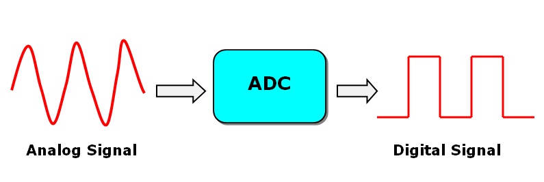
Analog to Digital Converter (ADC) is used to convert analog signal/voltage into its equivalent digital number so that microcontroller can process that numbers and make it human readable. The ADC characterized by resolution. The resolution of ADC indicates the number of digital values. Let’s take example: In LPC2148 microcontroller we have in-built 10-bit ADC. So for 10-bit ADC resolution is 10-bit and maximum value will be 210=1024. This means our digital value or discrete level lies between 0 to 1023. There is one more term important to understand while dealing with ADC and it is step size. Step size is the minimum change in input voltage which can be resolved by ADC. The concept of step size is closely associated with the resolution of ADC.
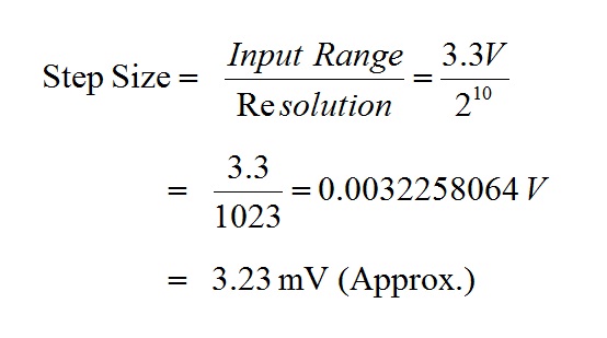
So in this case we can measure minimum 2.23 mV (Approx.) with our microcontroller. This is how step size defines an accuracy of ADC circuit.

Introduction: ADC in LPC2148 ARM7 Microcontroller
The ADC in LPC2148 ARM7 Microcontroller is 10-bit successive approximation analog to digital converter. The features are listed as:
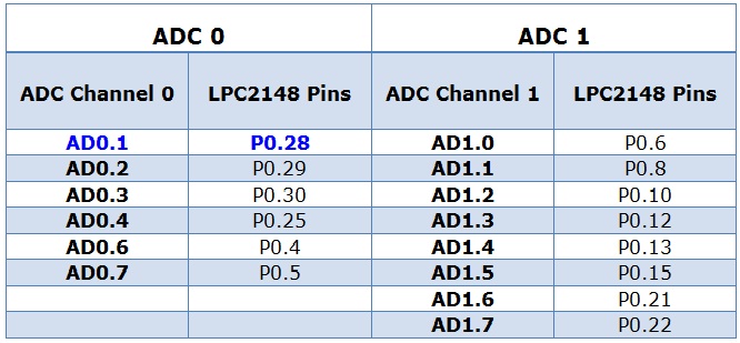
- LPC2148 has two inbuilt ADC Modules, named as ADC0 & ADC1.
- ADC0 has 6-Channels (AD0.1-AD0.6).
- ADC1 has 8-Channels (AD1.0-AD1.7).
- ADC operating frequency is 4.5 MHz (max.), operating frequency decides the conversion time.
- Supports power down mode.
- Burst conversion mode for single or multiple inputs.
There are several registers associated with ADC feature but we will mainly discussing about ADC Control Register (ADCR) & ADC Global Data Register (ADGDR). For more details on register description keep datasheet in hand UM10130, Chapter: 19.
Let’s have a look at table which illustrate ADC related channels and pins:
Registers of ADC in LPC2148 Microcontroller
There are several registers which will be used to setup and configure ADC feature in LPC2148. The two registers we will be concerning about: ADCR (A/D Control Register) and ADGDR (A/D Global Data register).
| Register Name | Function |
| ADCR | A/D Control Register: The ADCR register must be written to select the operating mode before A/D conversion can occurs. |
| ADGDR | A/D Global Data Register: This register contains ADC’s DONE bit and the result of the most recent A/D conversion. |
| ADSTAT | A/D Status Register: This register contains DONE and OVERRUN flag for all the A/D Channels, as well as the A/D interrupt flag. |
| ADGSR | A/D Global Start Register: This address can be written (in the AD0 address range) to start conversions in both A/D converters simultaneously. |
| ADINTEN | A/D Interrupt Enable Register: This register contains enable bits that allow the DONE flag of each A/D channel to be included or excluded from contributing to the generation of an A/D interrupt. |
| ADDRx | A/D Channel x Data: ‘x’ varies from 0 to 7 |
Programming Steps: ADC in LPC2148 ARM7 Microcontroller
- Configure input pin as analog input pin for ADC block
- Select channel we wish to use in our conversion
- Select clock for conversion & start conversion
- Wait for conversion to complete
- Read 10-bit conversion result
- Convert this result i.e. ADC output into decimal number
- Display reading on serial emulator or display device
Example Project: In this example project we will be using 10K POT to provide analog input at ADC Channel 0 i.e. Pin P0.28 of LPC2148 Microcontroller. To read ADC count from POT we will configure UART0 of LPC2148 and read data on terminal emulator (PuTTY). When we vary resistance of POT the change in ADC count will reflect on PuTTY terminal in real time. The circuit connection shown as:
CIRCUIT DIAGRAM: ADC in LPC2148 ARM7 Microcontroller

Source Code: ADC in LPC2148 ARM7 Microcontroller
/************************************************************/
/* PROJECT NAME: ADC (Analog to Digital Converter)	    */
/* Device:       LPC2148                                    */
/* Filename:     main.c                                     */
/* Language:     C                      	            */
/* Compiler:     Keil ARM				    */
/* For more detail visit www.binaryupdates.com		    */
/************************************************************/

#include <lpc214x.h>
#include "serial.h"
#include <stdio.h>

char String[]="Wel-Come to BINARYUPDATES.COM, ADC and UART Configured @LPC2148 \n\r Serial Communication @ 9600 baudrate, 8 bits, no Parity, 1 Stop bit\n\r\n";
char Newline[]="\n\r\n";

char adcreading[16] ;

void ADC_Init (void)
{
  PINSEL1 = 0x01000000 ;							// P0.28, AD0.1
}

unsigned int ADC_GetAdcReading()
{
  unsigned int adcdata;
  AD0CR = 0x01200302 ;								// Select AD0.1, Select clock for ADC, Start of conversion

  while(!((adcdata = AD0GDR) & 0x80000000))		// Check end of conversion (Done bit) and read result
  {
  }
  return((adcdata >> 6) & 0x3ff) ;				// Return 10 bit result
}

int main(void)
{
  unsigned int delay, adc;

  initClocks(); // Set CCLK=60Mhz and PCLK=60Mhz
  initUART0();
  ADC_Init() ;

  Send_String(String);

  while(1)
  {
    adc = ADC_GetAdcReading();
    sprintf(adcreading,"ADC0 CH1= %u",adc);  // read data in decimal format
    //sprintf(adcreading,"ADC0 CH1= 0x%03X",adc); // read data in hexx format
    Send_String(adcreading);
    Send_String(Newline);
    for(delay=0; delay<10000000; delay++); // delay
  }
}
Download Project: Click Here
The project is fully tested and functioning. We only have to compile and download .hex file onto LPC2148 Microcontroller. To see output on computer we will have to configure PuTTY to establish serial communication to read ADC results on PuTTY.
IMPORTANT: After loading .hex file, Make sure that you’re not into ISP Mode. We will be using same UART0 for programming as well as for receiving ADC result. In case if you’re using STK2148-UltraLite Board then turned off SW7 switches to read ADC Data on PuTTY.
Once we have done with all settings, just open console. And we will start receiving ADC results on PuTTY, sent by LPC2148 Microcontroller. Here is an output from our project:
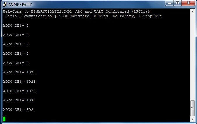
This is how we can program internal ADC in LPC2148 ARM7 Microcontroller to read analog input from any device. In future post we will explore topics such as multiple ADCs and External ADC interfacing etc. We hope this post will help you to get your ADC up-running. If you have any question then please feel free to drop comment. Thanks…!!!!