The bitwise or bit-level operator lay’s foundation for bitwise operations in embedded programming. We hope you already have sound knowledge of binary number systems in order to follow this tutorial. Many newbies found themselves confuse with Bitwise Vs. Boolean operations. A bitwise expression is used when we want to modify a variable by changing some or any of the individual bits of the variable. & and | are bitwise operators for AND & OR respectively. We’ll see in later part of this post, how it will be used to set, clear and extract a bit using bitwise operations. A Boolean expression is used when we want to know something about a variable is it equal to 12, is it greater than 12 or is it less than 5 etc. Boolean operators are: && (logical and), || (logical or), ! (logical not). X && Y returns TRUE only if both X and Y are TRUE. X || Y returns TRUE if either X or Y are TRUE.
Table of Contents
Basics of Bitwise Operations
Now let’s concentrate only on bitwise operations. We’ll learn how these bitwise operations allow’s us for Setting, Inverting, Toggling, Clearing, Extracting and Inserting bits in embedded programming. Here is a table which summarizes operations with 2-operands.
| A | B | A | B | A & B | A ^ B |
| 0 | 0 | 0 | 0 | 0 |
| 1 | 0 | 1 | 0 | 1 |
| 0 | 1 | 1 | 0 | 1 |
| 1 | 1 | 1 | 1 | 0 |
Let’s take variable A and B. We’ll perform bitwise operation on these two variables. This example will help you understand their operation. Let’s first declare these two variables:
| uint8_t A = 0x3B //00111011; uint8_t B = 0x96 //10010110; |

AND (& in C)
AND compares each bit and returns 1 if the two bits are 1 (TRUE) otherwise 0 (FALSE). So: C = A & B;
| 00111011………………..(A=0x3B) | |
| & | 10010110………………..(B=0x96) |
| 00010010 |
The value of C will be 0x12 or in binary 00010010. That is where there is a 1 in each bit for both values.
OR (| in C)
OR will return a 1 if there is a 1 in either value at that bit. So: C = A | B;
| 00111011………………..(A=0x3B) | |
| | | 10010110………………..(B=0x96) |
| 10111111 |
The value of C will be 0xBF or in binary 10111111
XOR (^ in C – Exclusive OR)
XOR will return a 1 if there is a 1 at that bit for either value but not both. For example, if bit position 5 for both values has a 1 then XOr returns a 0. But if only one has a 1 and the other has a 0 XOR returns a 1. So: C = A^B;
| 00111011………………..(A=0x3B) | |
| ^ | 10010110………………..(B=0x96) |
| 10101101 |
The value of C will be 0xAD or in binary 10101101.
NOT (! in C)
This returns the compliment of a value. This mean where there was a 0 there will now be a 1 and vice versa. So: C = ~(A);
| ! | 00111011………………..(A=0x3B) |
| 11000100………………..(C=0xC4) |
The value of C will be 0xC4 or in binary 11000100
Bitwise Shift Operators (<<, >>)
And then there are two shift operators – Left shift and Right shift. These operators shift the bits by the corresponding value, in other word’s move the bits. The sign << for left shift and >> for right shift. Here is an example:
| C = A << 2; // left shift A by 2 |
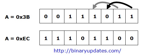
The value of C becomes 0xEC or in binary 11101100 after shifting 2-bits to the left.
| D = B >> 4; // right shift B by 4 |
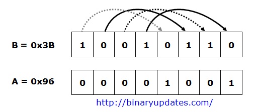
The value of D becomes 0x03 or in binary 00001001 after shifting 4-bits to right.
Setting bits, Inverting bits
Let’s say we have variable called bits and we have asked to set the bit-7. This can be achieved by writing this single line of code.
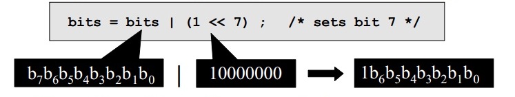
bits = bits | (1 << 7) ; /* sets bit 7 */
This would usually be written more succinctly as:
bits |= (1 << 7) ; /* sets bit 7 */
Inverting (toggling) is accomplished with bitwise-XOR. In following, example we’ll toggle bit-6.
bits ^= (1 << 6) ; /* toggle bit 6 */
Testing Bits
Form a mask with 1 in the bit position of interest, in this case bit-6. Then bitwise AND the mask with the operand. The result is non-zero if and only if the bit of interest was 1:
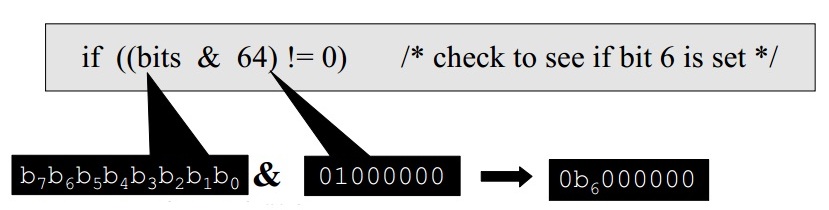
if ((bits & 64) != 0) /* check to see if bit 6 is set */
Same as:
if (bits & 0x64) /* check to see if bit 6 is set */
Same as:
if (bits & (1 << 6)) /* check to see if bit 6 is set */
Clearing Bits
Let’s say if we want to clear bit-7. This can be accomplished using bitwise-AND operator

Mask must be as wide as the operand! if bits is a 32-bit data type, the assignment must be 32-bit:
bits &= ~(1L << 7) ; /* clears bit 7 */
Extracting Bits
Let’s say we have given a 32-bit number and we asked to extract bits from it. Assume that 32-bit number in hex is 0xD7448EAB. In binary= 1101 0111 0100 0100 1000 1110 1010 1011. Now we have asked to extract 16-bits from bit number 10 through 25.
To extract the bits first we have to use bitwise operator in combination with a bit mask to extract bits 10 through 25. The masking value will be 0x3FFFC00. Now we have two ways we can achieve result.
Method-I
unsigned int number = 0xD7448EAB;
unsigned int value = (number & 0x3FFFC00) >> 10;
Method-II
unsigned int number = 0xD7448EAB;
unsigned int value = (number >> 10) & 0xFFFF;
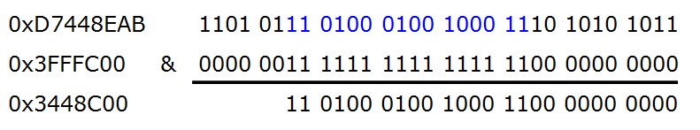
Now if we follow Method-I and after equating. We’ve got 0x3448C00 (In binary 11010001001000110000000000). When we shift 10 bits to right, we’ll get 0xD123 i.e. in binary 1101000100100011.
Monitoring Specific Bit
Monitoring specific bit in register is very important. In Embedded programming, very often we need to read status of flag bit in hardware register. These flag bit controls or indicate hardware feature. Also they are every useful while reading, writing data to and from microchip. So we continuously monitor these bits in register to carry out desired function by microchip. Let’s say if we want to monitor 4th bit for any change, we’ll write function as below:
while( bits & (1<<4) ) // monitor for 4th bit changing from 0 to 1
{
	.......
	.......
}
The 4th bit of register bits is ‘1’ the result of (bits & (1<<4)) will always be zero. When 4th bit is ‘1’ then (bits & (1<<4)) will be equal to (1<<4) which is greater than 0 and so this evaluates as TRUE condition and code inside while loop get executed.
Now let’s say if we want to monitor 4th bit state from 1 to 0. In this case, we only need to negate the condition inside of while statement.
while( ~(bits & (1<<4)) ) // monitor for 4th bit changing from 1 to 0
{
	.......
	.......
}
Bitwise operators save memory and it is fast. This all leads to improve performance. I hope now you know that why bitwise operations in embedded programming used such a widely. If you have any questions or suggestions then feel free to leave a comment.