In our previous tutorial, we have seen how to create new KEIL uVision Project for LPC2148 Microcontroller. Also we have seen how to program ARM7 LPC2148 microchip. Here we’ll explore the use of GPIO. GPIO (General Purpose Input Output) pins are the most basic peripherals in any microcontroller. As a first tutorial in this series we’ll Blink LED with ARM7 LPC2148 Microcontroller. Although it’s simple task but still we feel good to get start with. Before we proceeds any further to blink LED (Light Emitting Diode).
Let’s discuss about GPIO. GPIO lines of any microcontroller can be used mainly to perform two things. One is to generate digital signal and second one is to read a digital signal. In LPC2148 microcontroller most of port pins are multiplexed, this means they’re allowed to provide multiple functions. Configuring GPIO to use different function is out of the scope of this tutorial. Just keep in mind that by default: all functional pins i.e. Pins on PORT0 and PORT1 are set to be as GPIO so we can directly use them in our example project.

Here we’ve listed some GPIO related registers and its functions. We need to replace ‘x’ with the port number to get the register name. Say for example: IOxPIN register becomes IO0PIN when used for PORT0 and IO1PIN when used for PORT1. These all register names defined in the header file “lpc2148.h” Register names defined in the header file are nothing but a pointer which holds the address of actual register in LPC2148. (‘x’ represent port number).
GPIO Related Registers In LPC2148
| IOxPIN | This register can be used to read or write values directly to the pins. Regardless of the direction set for the particular pins. It gives the current state of GPIO pin when read. |
| IOxDIR | This is the GPIO direction control register. Setting a bit to ‘0’ in this register will configure the corresponding pin to be used as input while setting it to ‘1’ will configure it as output. |
| IOxSET | This register can be used to drive an ‘output’ configured pin to logic 1 i.e. HIGH. Writing zero does not have any effect and hence it can’t be used to drive a pin to Logic 0 i.e. LOW. For driving pins LOW IOxCLR is used which is explained as below: |
| IOxCLR | This register can be used to drive an ‘output’ configured pin to logic 0 i.e. LOW. Writing zero does not have any effect and hence it can’t be used to drive a pin to Logic 1. |
Video: Blink LED with ARM7 LPC2148
Example: Blink LED with ARM7 LPC2148
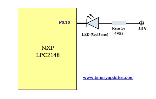
Let’s have a look at example project where we’ll blink LED connected to Pin P0.10. Please make sure that this LED connected in common anode configuration. Refer the circuit connections as:
While writing an application to blink LED, we have to follow general steps:
- Initialize a microcontroller system, which take care setup procedure like powering up peripherals, set clock rate etc.
- Connect necessary pin using pin connect block. The purpose of pin connect block is to configure microcontroller pin to desired function. By default GPIO is enabled.
- And then set or clear the bit of respective pin to turn ON & OFF LED
#include <lpc214x.h>

unsigned int delay;

int main(void)
{
  IO0DIR = (1<<10);   // Configure P0.10 as Output

  while(1)
  {
    IO0CLR = (1<<10);	// CLEAR (0) P0.10 to turn LED ON
    for(delay=0; delay<500000; delay++); // delay
    IO0SET = (1<<10);	// SET (1) P0.10 to turn LEDs OFF
    for(delay=0; delay<500000; delay++); // delay
  }
}
To download Project: Click Here
CODE EXPLANATION:
This complete program consists of only few lines of code. Let me slice down into pieces to elaborate each line
#include <lpc214x.h>
This include statement adds standard header file for all LPC214x series of microcontrollers. All register names has been defined in lpc214x.h file.
IO0DIR = (1<<10); // Configure P0.10 as Output
Since we have connected LED to Pin P0.10. We have to set Pin into an output mode. As P0.10 belongs to PORT0. The direction control bit in IO0DIR register been used to configure this pin.
while(1)
{
  IO0CLR = (1<<10);		       // CLEAR (0) P0.10 to turn LED ON
  for(delay=0; delay<500000; delay++); // delay
  IO0SET = (1<<10);		       // SET (1) P0.10 to turn LEDs OFF
  for(delay=0; delay<500000; delay++); // delay
}
In this never ending while loop. We first have to clear a bit using IO0CLR=(1<<10), this is how we can make P0.10 to become LOW (LED turned ON). IO0SET=(1<<10), would make output HIGH (LED turned OFF) for Pin P0.10. We have for loop in between which generate significant delay between the process of turning LED ON and OFF.
In future we’ll explore delay function to generate accurate time delay. We hope this tutorial will be helpful to get you started. In next tutorial we’ll learn how to add switch to our LPC2148 Microcontroller project.