This tutorial is about Interrupt in LPC2148 ARM7 Microcontroller. As in our previous post we have programmed timer in LPC2148 to generate precise delay. Here we’ll generate interrupt to perform same task. Throughout this tutorial series we’ll use interrupt with several peripherals of LPC2148 ARM7. Before we proceed any further let’s refresh the concept of interrupt and then we’ll have a look at timer interrupt in LPC2148.
What is Interrupt or ISR?
In general, an Interrupt is a signal from device attached to a computer or from a program within controller that causes main program to stop and figure out what to do next. ISR (Interrupt Service Routine) is executed when an interrupt occurs. A section of a program that takes control when an interrupt is received and perform the operations required to service the interrupt.
How Interrupt Works?
- Whenever any device needs service of microcontroller, the device notifies the microcontroller by sending interrupt signal.
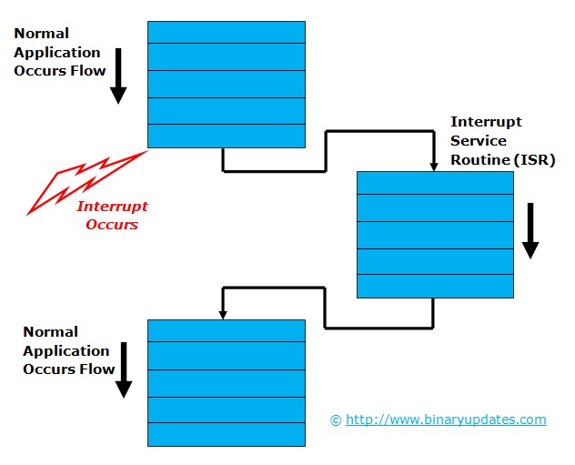
- Upon receiving an interrupt signal, the microcontroller stops or interrupt main program flow and saves the address of the next instruction (PC) on the stack pointer (SP).
- It jumps to a fixed location in memory, called interrupt vector table that hold the address of the ISR (Interrupt Service Routine). Each interrupt has its own ISR. The microcontroller gets the address of the ISR from the interrupt vector table and jump to it.
- It starts to execute the Interrupt Service Routine until it reaches the last instruction of the subroutine which is RETI (Return from Interrupt). RETI not used in C Coding. (Fig: Interrupt and ISR Relation)
- Upon executing last instruction in Interrupt Service Routine the microcontroller returns to the place where it left off or interrupted previously. And first, it gets the program counter (PC) address from the stack pointer by popping the top two bytes of the stack into the PC.
- Then it starts to execute from that address and continue executing main program.

Interrupt in LPC2148 ARM7 Microcontroller
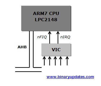
In LPC2148 ARM7 Microcontroller, The VIC is a component from ARM prime cell range of modules which is highly optimized interrupt controller. The VIC is used to handle all the on-chip interrupt sources from peripherals. Each interrupt source is connected to the VIC on a fixed channel. Our application software can connect these channels to the CPU interrupt lines (FIQ, IRQ)
- In total, ARM supports 32-interrupt request input
- In ARM, special controller is incorporated to deal with the interrupt called VECTORED INTERRUPT CONTROLLER (VIC)
- The AMBA (Advance High Performance Bus) is used for interface vectored interrupt controller to the ARM7 Core (LPC2148) in our case.
The vector Interrupt Controller (VIC) takes 32-interrupt request input and assigned them programmably into 3-categories, listed below:
| FIQ | Fast Interrupt Request: For fast, low latency interrupt handling. FIQ have highest priority followed by interrupt vector 0-31. Only single FIQ source at a time is generally used in a system |
| Vectored IRQ | Vectored Interrupt Request: VIRQ have medium priority. Vectored Interrupt Controller has 32 vectored interrupt slots out of which 16 slots are used for vector addressing. Each slot contain vector address register & vector control register |
| Non-Vectored IRQ | Non-Vectored Request: Non Vectored IRQ has lowest priority. The VIC is capable of handling 16 peripherals as a vectored interrupt and at least one as an FIQ Interrupt. If in case there are more than 17 interrupt sources on chip, any extra interrupt can be serviced as a Non-Vectored Interrupt. |
REGISTERS: INTERRUPT in LPC2148 ARM7
There are bunch of interrupt registers we’ll be using to setup interrupt in LPC2148 ARM7 Microcontroller. We recommend reader to keep datasheet in hand. We’ll explore few of those register while explaining program code. Please follow datasheet[Chapter: 7.4 Page No: 66-74]
STEPS: To Program Interrupt in LPC2148 ARM7 Microcontroller
- Enable the Interrupt
- Select Interrupt Type i.e. IRQ or FIQ
- If FIQ then ISR should be written as:
__fiq void FIQ_Handler()
{

}
- If Vectored IRQ then we have to access the registers of vectored IRQ i.e. control register and address register and write ISR as:
__irq void ISR_Name()
{

}
- If it is Non-Vectored IRQ then access Default Address Register:
__irq void ISR_Name()
{

}

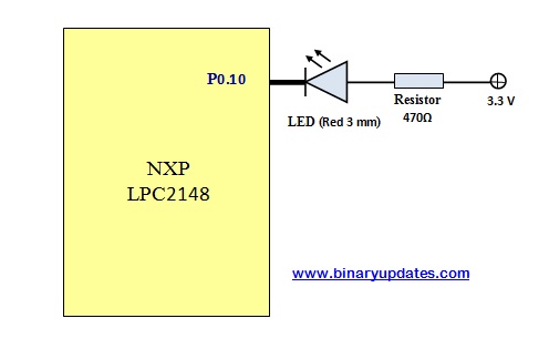
Example Project: To use interrupt in our example project. We’ll use Timer to show usage of interrupt in LPC2148 ARM7 Microcontroller. As we’ve seen Timer in our previous post. I believe our brain is still warm with it. To keep simplicity in our example project we’ll blink LED when interrupt is generated after every 0.5 Sec.
#include <lpc214x.h>

void initClocks(void);
void initTimer0(void);
__irq void timer0ISR(void);

int main(void)
{
   initClocks(); 	// Initialize PLL to setup clocks
   initTimer0(); 	// Initialize Timer0
   IO0DIR = (1<<10);	// Configure pin P0.10 as Output
   IO0PIN = (1<<10);

   T0TCR = (1<<0); 	// Enable timer

   while(1); 		// Infinite Idle Loop
}


void initTimer0(void)
{
  T0CTCR = 0x0;		//Set Timer Mode
  T0PR = 60000-1; 	//Increment T0TC at every 60000 clock cycles
      //60000 clock cycles @60Mhz = 1 mS

  T0MR0 = 500-1; 	  //Zero Indexed Count-hence subtracting 1
  T0MCR = (1<<0) | (1<<1);//Set bit0 & bit1 to Interrupt & Reset TC on MR0

  VICVectAddr4 = (unsigned )timer0ISR; //Pointer Interrupt Function (ISR)
  VICVectCntl4 = (1<<5) | 4; 	//(bit 5 = 1)->to enable Vectored IRQ slot					//bit[4:0]) -> this the source number
  VICIntEnable = (1<<4);	// Enable timer0 interrupt

  T0TCR = (1<<1); 		// Reset Timer
}

__irq void timer0ISR(void)
{
  long int readVal;
  readVal = T0IR; 	// Read current IR value
  IO0PIN ^= (1<<10); 	// Toggle LED at Pin P0.10
  T0IR = readVal; 	// Write back to IR to clear Interrupt Flag
  VICVectAddr = 0x0; 	// End of interrupt execution
}

void initClocks(void)
{
  PLL0CON = 0x01;         //Enable PLL
  PLL0CFG = 0x24;         //Multiplier and divider setup
  PLL0FEED = 0xAA;        //Feed sequence
  PLL0FEED = 0x55;

  while(!(PLL0STAT & 0x00000400)); //is locked?

  PLL0CON = 0x03;        //Connect PLL after PLL is locked
  PLL0FEED = 0xAA;       //Feed sequence
  PLL0FEED = 0x55;
  VPBDIV = 0x01;         //PCLK is same as CCLK i.e.60 MHz
}
Download Project: Click Here
CODE EXPLANATION:
Let’s break down a code into pieces for detail explanation. We’ll try to understand what each line stands for. You can see, we have only added one extra function into previous timer example program.
void initTimer0(void)
{
  T0CTCR = 0x0;		//Set Timer Mode
  T0PR = 60000-1; 	//Increment T0TC at every 60000 clock cycles		                        //60000 clock cycles @60Mhz = 1 mS

  T0MR0 = 500-1; 	  //Zero Indexed Count-hence subtracting 1
  T0MCR = (1<<0) | (1<<1);//Set bit0 & bit1 to Interrupt & Reset TC on MR0

  VICVectAddr4 = (unsigned )timer0ISR; //Pointer Interrupt Function (ISR)
  VICVectCntl4 = (1<<5) | 4; 	//(bit 5 = 1)->to enable Vectored IRQ slot			       //bit[4:0]) -> this the source number
  VICIntEnable = (1<<4);	// Enable timer0 interrupt

  T0TCR = (1<<1); 		// Reset Timer
}
In this function we have configured Timer0 and Interrupt feature. As we’ll be running PCLK at 60 MHz, we’ve to set prescale value to be 60000-1= 59999 into T0PR register so that after every 60000 clock cycle we increment T0TC register(60000 clock cycle at 60 MHz allows to generate 1 ms resolution). Now setting 500-1 = 499 into T0MR0 register which trigger interrupt at every 500 milliseconds. We also have to set bit 0 and 1 into T0MCR register to interrupt and reset Timer Counter Register (TC) in Match Register (MR0). VICVectAddr4 = (unsigned)timer0ISR, used to setup pointer to interrupt service routine (In our case timer0ISR). Basically Vector Address Register store the address of the function i.e. ISR and used to assign or enable vector IRQ slot. We also have to enable slot and set priority for interrupt. VICVectCntl4=(1<<5) | 4, here setting bit 5 in Vector Control Register4 will enable slot which has assigned by VICVectCntl4 i.e. here in this case it is ‘4’. Writing decimal 4 would set interrupt source i.e. Timer0 as an interrupt. After setting all interrupt related registers we have to enable Timer0 interrupt by setting VICVectIntEnable = (1<<4) and Reset Timer0 by setting bit 1 to become HIGH into T0TCR register.
INTERRUPT SOURCES TO VECTORED INTERRUPT CONTROLLER (VIC)
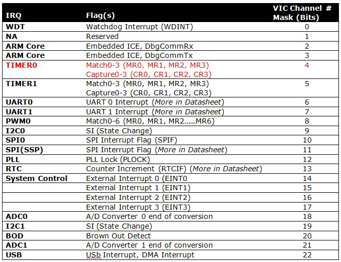
For More details on interrupt sources, please visit datasheet [Chapter 7.5 Interrupt Sources, Page No:73-74]
__irq void timer0ISR(void)
{
  long int readVal;
  readVal = T0IR; 	// Read current IR value
  IO0PIN ^= (1<<10); 	// Toggle LED at Pin P0.10
  T0IR = readVal; 	// Write back to IR to clear Interrupt Flag
  VICVectAddr = 0x0; 	// End of interrupt execution
}
This is an Interrupt Service Routine (ISR). As we have used Timer0 as a source of interrupt. An MR0 match event which raises an IRQ (Interrupt ReQuest). Because we know Timer 0 is source of interrupt so read current value in Timer0’s Interrupt Register i.e. T0IR. When MR0 match event occurs we’ll toggle LED connected to Pin P0.10. We also have to make sure to clear interrupt flag ‘T0IR = readVal’ and call for end of interrupt by setting VICVectAddr= 0x0).