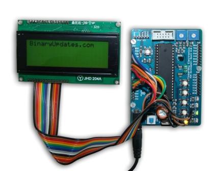
In this tutorial we will learn how to interface LCD with AVR Microcontroller specifically ATmega32A. This could be very cool experiment to add display to your microcontroller based projects. These LCD modules are very efficient to receive information and control commands from microcontroller. There are plenty of different manufacturer and type of display available in market. The one we are interested in here is JHD204A (20×4 LCD Module) which is basically china made cheap and available anywhere in retails shops. I am not a personally a fan of this display but this is the only cheapest LCD module available with me at this moment.

JHD 204A/JHD16x2 is compatible with HD44780 LCD
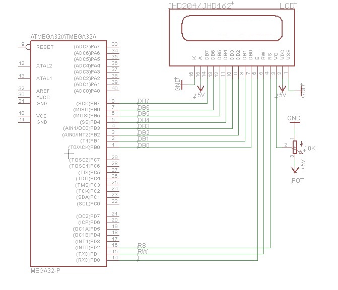
This is also probably the best tutorial for people who want to use LCD without understanding much about working parts of it. As explaining about each part of LCD in detail is nearly impossible so I decided to make this article know how or instruction based. The first step for this experiment is to make basic connections between pins of LCD module which are in total 16 with ATmega32A microcontroller. If you want to make sure that either your LCD is working or not then please follow link
Interface LCD JHD20x4/JHD16x2 to AVR Atmega32A
Click on image to zoom (better picture)
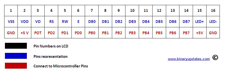
click on image for Zoom
Once you finished with basic connection between LCD module and ATmega32A. We can jump right into programming so that we will show custom message on LCD screen. Before we get into it one must understand the sequence of operation we have to perform such as initialization, check busy state, and then write character or string to flash onto LCD screen. It would be so much if I explain role of each function into program either I prefer to recommend you to look into code and datasheet of LCD. If you spend enough time to leer with it you will find name of functions in code itself are pretty explanatory. Let’s have a look into code snippet.
Source Code: interface LCD with AVR Microcontroller
/*
 * This example demo for interfacing LCD(20x4) in 8-bit mode
 * Author.......: Umesh Lokhande <www.binaryupdates.com>
 * Project......: LCD Test (20x4) in 8-bit mode
 * Created......: 12/16/2014 6:07:06 AM
 * Target.......: ATMega32 at 1 MHz
 */

#define F_CPU 1000000

#include <avr/io.h>
#include <util/delay.h>

#define data_lcd PORTB
#define data_dir DDRB
#define control_lcd PORTD
#define control_dir DDRD

#define enable 0 // responsible to accept information
#define rw 1     // responsible for read and write
#define rs 2     // decide sent info. is character/control

void check_lcd(void);
void on_and_off(void);
void send_command(unsigned char command);
void send_character(unsigned char character);
void send_string(char *StringofCharacters);

int main(void)
{
 control_dir |= (1<<rs) | (1<<rw) | (1<<enable); /* set control signal in output mode */
 _delay_ms(15);

 send_command(0x01); /* Clear display */
 _delay_ms(1.52);
 send_command(0x38); /* Function Set (8-bit mode) */
 _delay_us(37);
 send_command(0x0C); /* Display On-OFF Control */

 /*message that sent to screen */
 send_string("BinaryUpdates.com");

 while(1)
 {

 }
}

/* check if LCD is busy------------This is
 only time when we are reading from LCD */

void check_lcd()
{
 data_dir = 0; // data direction as input
 control_lcd |= 1 << rw; // put LCD in read mode, RW ON
 control_lcd &= ~(1 << rs); // put LCD in command mode RS OFF
 while(data_lcd >= 0b10000000) // D7 pin will be 1 if LCD is busy
 {
 on_and_off();
 }
 data_dir = 0xFF;
}

/* Keep enable signal on and off to see information on LCD */
void on_and_off()
{
 control_lcd |= 1 << enable;
 asm volatile("nop");
 asm volatile("nop");
 control_lcd &= ~(1 << enable);
}

/* send command to instruct lcd */
void send_command(unsigned char command)
{
 check_lcd();
 data_lcd = command;
 control_lcd &= ~((1<<rw) | (1<<rs)); // RW-OFF & RS-OFF
 on_and_off();
 data_lcd = 0;
}

/* send character to lcd */
void send_character(unsigned char character)
{
 check_lcd();
 data_lcd = character;
 control_lcd &= ~(1 << rw); // RW-OFF
 control_lcd |= 1 << rs; // RS-ON
 on_and_off();
 data_lcd = 0;
}

/* send string on lcd */
void send_string(char *StringofCharacters)
{
 while(*StringofCharacters>0)
 {
 send_character(*StringofCharacters++);
 }
}
Please download complete project at LCDTest