This tutorial is about how to use pulse width modulation in AVR Atmega32A Microcontroller. PWM(Pulse Width Modulation) is an interesting phenomenon which used to generate analog signals from digital device. AVR microcontroller has dedicated hardware for PWM signal generation which reduce the load of generation of PWM signal from software. It is something similar to tell internal hardware of microcontroller to generate PWM signal of specific duty cycle. There are many different applications are associated with PWM for example brightness control of LED, controlling servo or DC motors, sound output, producing approximated analog waveform.

In broader sense the period of PWM is what creates a frequency and it represented as length of time. The period is the place where digital signal count to be high and then goes low and the proportion between is called “duty cycle”. The period is selected at beginning and does not change. Usually it decided as, if period is longer then it represents slower frequency and if period is shorter represent higher frequency (fast). Usually it supposed that frequency of PWM is how many periods can fit within one second. There are three different modes available to general pulse width modulation:
- Fast PWM
- Phase Correct PWM
- Frequency and Phase Correct PWM
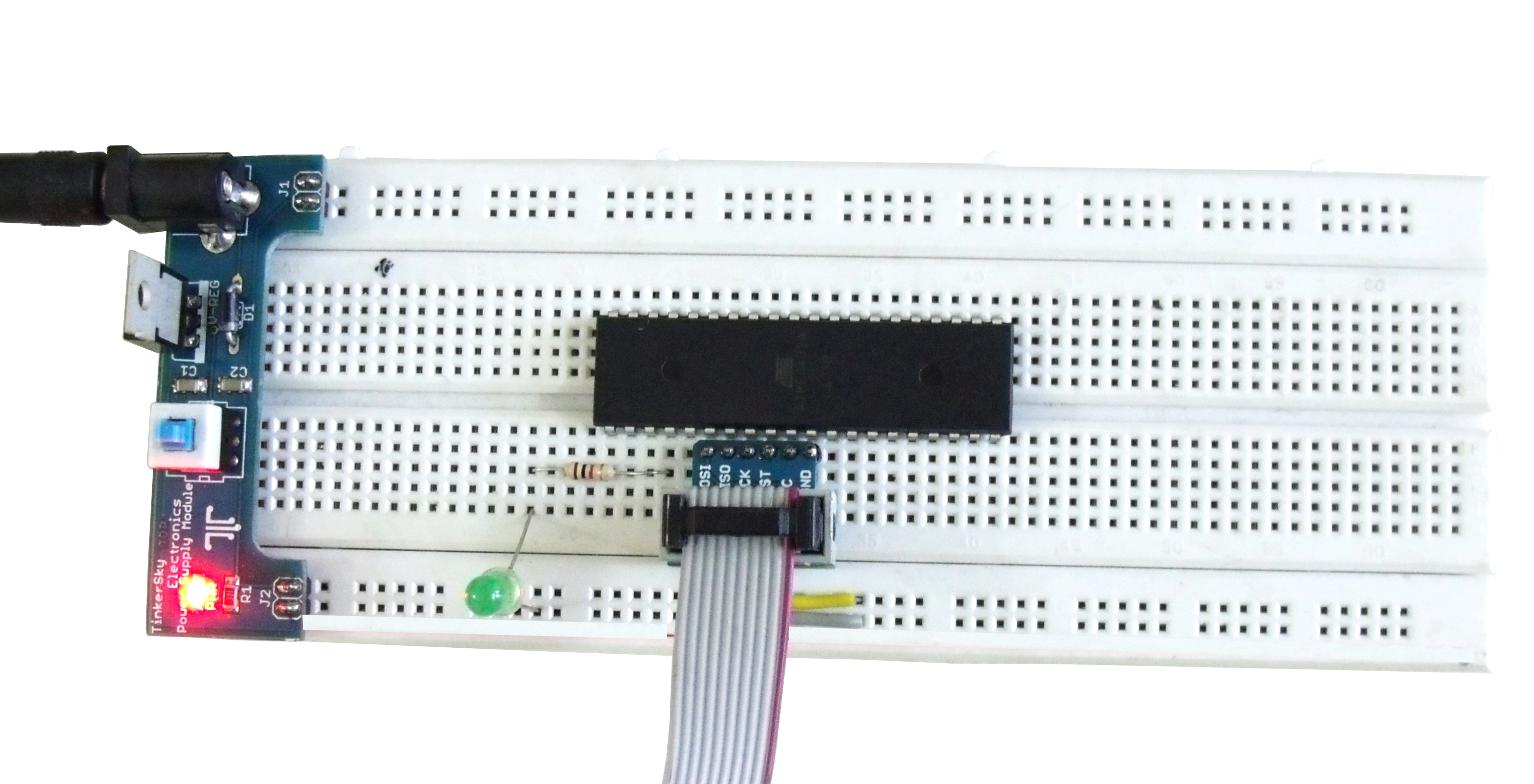
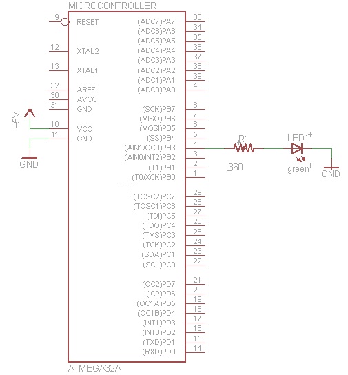
Just because lack of time we are not discussing about each one in detail. Maybe in future blog post and article will cover more modes, here in this case we are using fast PWM mode with AVR microcontroller’s 8-bit TIMER 0. We have chosen TIMER 0 because it’s an 8-bit with maximum count 255. This is enough to implement classic example of dimming or brightness control for LED. Other hand TIMER 1 is 16-bit with maximum count 65535 with two registers TCCR1A & TCCR1B which introduce more complexity for beginner. To keep simplicity for beginner to understand concept, I have chosen Timer 0. In this example we are going to connect green LED with current limiting resistor 330Ω to “PB3” pin of ATmega32A.
Circuit Schematic: Pulse Width Modulation In AVR Atmega32A Microcontroller
Click on Image for better picture
This video is step-by-step guide with code explanation:
C Program: PWM In AVR Atmega32A
#include <avr/io.h>
#include <util/delay.h>

void InitPWM()
{
   TCCR0|=(1<<WGM00)|(1<<WGM01)|(1<<COM01)|(1<<CS00);
   DDRB|=(1<<PB3);
}

void SetPWMOutput(uint8_t duty)
{
   OCR0=duty;
}

void Wait()
{
 _delay_loop_2(3200);
}

void main()
{
   uint8_t brightness=0;
   InitPWM();

   while(1)
   {
      //Now Loop with increasing brightness
      for(brightness=0;brightness<255;brightness++)
      {
         SetPWMOutput(brightness);
         Wait();
      }

      //Now Loop with decreasing brightness
      for(brightness=255;brightness>0;brightness--)
      {
         SetPWMOutput(brightness);
         Wait();
      }
   }
}
This is it for this tutorial and I hope now you can use PWM in AVR Atmega32A Microcontroller. In next tutorial, we will learn how to interface character LCD with AVR ATmega32A Microcontroller. If you have any questions then feel free to leave a comment.