In this tutorial, we will learn how to use switch with 8051 Microcontroller. We’ll turn LED ON when switch is pressed and turn LED OFF when switch is released. Here we are going to program 89V51RD2 and you can use same code with any other derivatives of 8051(MCS51) family. Here in this example project we will use Pin 6 of PORT2 that is P2.6 Pin as Input. Please note that PORT1, PORT2 and PORT3 of 8051 have internal pull up resisters and PORT0 don’t have internal pull up or pull down resisters.
If you want to use any pin from PORT1, PORT2, PORT3 as input then there is no need to attach external pull up resistor but if you are going to use PORT0 pin as input then you must add external pull up resistor. Here in this case we will use PORT2 pin as input so there is no need to attach external pull up resistance. And as there is pull up resister to P2.6 we are going to use active LOW switch.
Circuit Diagram: Switch with 8051 Microcontroller
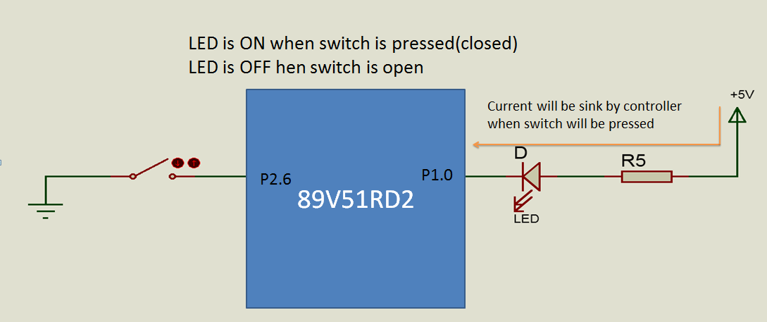
Connection Diagram: Switch with 89V51RD2 Microcontroller
The circuit connection remains the same for any other derivative of 8051 (MCS-51 family). Resistance R1 and Capacitor C3 is used for resetting controller when we give power to circuit (at startup). And we can always use Reset Switch to RESET Microcontroller manually at any time. When we press Reset Switch, voltage at reset pin (Pin No. 9) goes high which resets controller. Crystal X1 and two capacitors C1 and C2 operating in parallel resonance to provide approximately 11.0592MHz clock to our microcontroller. Do connections according to following circuit diagram after burning program into your 8051 IC. As current sinking capability of TTL logic family ICs is more than current sourcing capability, we have connected LED in active low mode to P1.0 pin and Switch to P2.6 in active low mode as there is internal pull up for PORT 2.

Program Code for keil:
//we are going to use P1.0 as output
//and P2.6 as input

#include<reg51.h>

sbit LED=P1^0;	// for LED
sbit SW=P2^6;	// for switch(Active LOW)

void main()
{
  SW=1; 	// Making switch pin as input
  LED=1;	// Making LED OFF initially
  while(1) //never ending loop
  {
    if(SW==1)
    {
    LED=0; // LED ON
    }
    else
    {
    LED=1;// LED OFF
    }
  }
}
Code Explanation:
#include<reg51.h>
This include statement add header file for the register definitions and SFRs(Special Function Registers) of 8051. This is standard header file for 8051 MCU.
sbit LED=P1^0
sbit data type is useful to access single bit addressable register. It allows access to single bits of SFR (Special Function Registers). Some of SFRs are bit addressable. We can use sbit to access individual bits of the port. As we have accessed P1.0 Pin by name LED.
sbit SW=P2^6
for accessing P2.6 pin by name SW.
void main()
Our program execution starts from here.
while(1)
This condition always holds true so this loop is never ending loop. And as we want to check for switch condition (weather it is pressed or not) continuously, we have used this infinite loop.
if(SW==0)//if switch is pressed
{
  LED=0; // LED ON
}
This loop executes only when switch is Pressed(SW=0). And when switch is not pressed then else loop executes.
else// switch is open
{
 LED=1;// LED OFF
}
This loop executes when if statement is false(SW=1) that is when switch is open.
This is how we can add switch with 8051 Microcontroller. In next tutorial we’ll see how to use timer feature and add time variable to our microcontroller project. We’ll learn how to configure timer in 8051 for accurate control of any application.This could be very cool example project. Thank’s guys….Please feel free to leave comments…!!!