This tutorial is about external interrupt in LPC2148 ARM7 Microcontroller. As in our previous post we’ve used interrupt to toggle LED after every half a second. In this example project we’ll configure external interrupt input using switch to generate beep, Also we’ll interface buzzer with LPC2148 microcontroller. Let’s understand first
What is External Interrupt?
Interrupt caused by an external source such as external switch, sensor or monitoring device. These interrupt are special events that require immediate attention. An interrupt can be configured to be set off by a variety of triggers. Say for example: the chip awaits a signal change on a pin connected to a switch or sensor and timed interrupts. Seven Pins of PORT0 on LPC2148 Microcontroller can be configured as external interrupt input. The pin description is given as below:
| Pin Name | Pin Direction | Pin Description |
| EINT0 | External Interrupt Input 0 | Pins P0.1 and P0.16 can be selected to perform EINT0 function |
| EINT1 | External Interrupt Input 1 | Pins P0.3 and P0.14 can be selected to perform EINT1 function |
| EINT2 | External Interrupt Input 2 | Pins P0.7 and P0.15 can be selected to perform EINT2 function |
| EINT3 | External Interrupt Input 3 | Pins P0.9, P0.20 and P0.30 can be selected to for EINT3 |

Registers: External Interrupt in LPC2148 ARM7
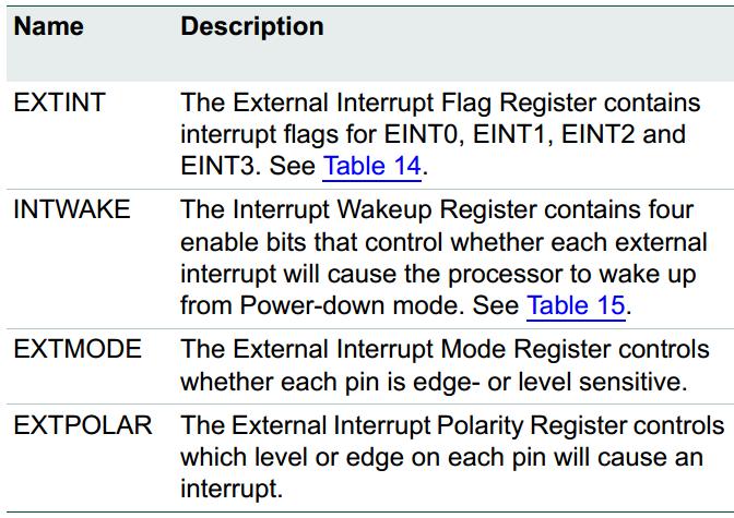
The external interrupt function has four registers associated with it. The EXTINT register contains the interrupt flags, and the EXTWAKEUP register contains bits that enable Individual external interrupts to wake up the microcontroller from Power-down mode. The EXTMODE and EXTPOLAR registers specify the level and edge sensitivity parameters. [Refer datasheet page no.27 Chapter: 4.5]
Example Project: External Interrupt in LPC2148 ARM7
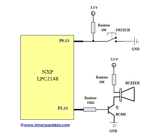
We will be using Pin P0.15 as an external interrupt pin. On our development board we also have buzzer connected to Pin P1.15 of LPC2148. The schematic is illustrated in figure below:
The details provided in explanation section, about how to configure the Pins P0.15 as external interrupt (EINT) input. First have a look at program:
/************************************************************/
/* PROJECT NAME: EXTERNAL INTERRUPT	                    */
/* Device:       LPC2148             			    */
/* Filename:     ExtInt.c                                   */
/* Language:     C                      	            */
/* Compiler:     Keil ARM            		   	    */
/* For more detail visit www.binaryupdates.com		    */
/************************************************************/

#include <LPC214x.H>

void delay(int count);
void init_ext_interrupt(void);
__irq void Ext_ISR(void);

int main (void)
{
  init_ext_interrupt();   // initialize the external interrupt

  while (1)
  {
  }
}

void init_ext_interrupt()  //Initialize Interrupt
{
  EXTMODE = 0x4;           //Edge sensitive mode on EINT2

  EXTPOLAR &= ~(0x4); 	   //Falling Edge Sensitive

  PINSEL0 = 0x80000000;    //Select Pin function P0.15 as EINT2

  /* initialize the interrupt vector */
  VICIntSelect &= ~ (1<<16);        	// EINT2 selected as IRQ 16
  VICVectAddr5 = (unsigned int)Ext_ISR; // address of the ISR
  VICVectCntl5 = (1<<5) | 16;			//
  VICIntEnable = (1<<16);           	// EINT2 interrupt enabled

  EXTINT &= ~(0x4);
}

__irq void Ext_ISR(void) // Interrupt Service Routine-ISR
{
 IO1DIR |= (1<<25);
 IO1CLR |= (1<<25); 	 // Turn ON Buzzer
 delay(100000);
 IO1SET |= (1<<25); 	 // Turn OFF Buzzer

 EXTINT |= 0x4; 		 //clear interrupt
 VICVectAddr = 0; 	 // End of interrupt execution
}

void delay(int count)
{
  int j=0,i=0;

  for(j=0;j<count;j++)
  {
    /* At 60Mhz, the below loop introduces
    delay of 10 us */
    for(i=0;i<35;i++);
  }
}
Download Project: Click Here
Initialization Steps: External Interrupt in LPC2148 ARM7
- Configure Pin Function
- Select Edge/Level sensitive
- Choose Signal Polarity
- Clear EINT Flag
After completing these steps, we need to determine the interrupt type generated by EINT inputs: Normal Interrupt Request (IRQ) or Fast Interrupt Request (FIQ).
Code Explanation:
To understand program we only have to discuss two functions, void int_ext_interrupt() and _irq void Ext_ISR(void). In void int_ext_interrupt(); we’ll initialize interrupt vector and call ISR when interrupt occurs. Whereas in _irq void Ext_ISR(void) function, we’ve set action to be performed while ISR been called (here in our example we’ll generate beep for a second). Let’s breakdown code into pieces:
void init_ext_interrupt()  //Initialize Interrupt
{
  EXTMODE = 0x4; 	   //Edge sensitive mode on EINT2
  EXTPOLAR &= ~(0x4); 	   //Falling Edge Sensitive
  PINSEL0 = 0x80000000;    //Select Pin function P0.15 as EINT2

  /* initialize the interrupt vector */
  VICIntSelect &= ~ (1<<16);        	// EINT2 selected as IRQ 16
  VICVectAddr5 = (unsigned int)Ext_ISR; // address of the ISR
  VICVectCntl5 = (1<<5) | 16;
  VICIntEnable = (1<<16);           	// EINT2 interrupt enabled

  EXTINT &= ~(0x4);
}
After setting edge sensitive mode and polarity to become falling edge sensitive to interrupt signal. We have to modify PINSEL0 register to change the function of pin P0.15 from General Purpose IO i.e. GPIO to External Interrupt 2 (EINT2). Now we must modify the vector control 5 register (VICVectCntl5). There are 16 of these registers (VICVectCntl0 to VICVectCntl15), each controlling a vector IRQ Slot. VICVectCntl0 has highest priority, while VICVectCntl15 has the lowest priority. Let’s modify VICVectCntl5; Bit fields 4:0 is for the number of the interrupt request. External Interrupt2 (EINT2) is channel 16. We want this interrupt channel to be assigned to IRQ Slot5. So we must modify register VICVectCntl5 to allow this we load bit fields 0:4 of VICVectCntl5 with “(1<<5) | 16” because we want channel 16 in this IRQ slot. Bit field of ‘5’ of VICVectCntl5 is for IRQ slot enabled i.e. (1<<5). When this bit field is 1, this vectored IRQ slot is enabled. (THIS IS NOT SAME AS ENABLING AN INTERRUPT), this is just to enable the vectored IRQ slot. Disabling a vectored IRQ slot in a VICVectCntlX register does not disable the interrupt: it just changes the interrupt from Vectored to Non-Vectored form.
Now it’s time to modify the vector address register (VICVectAddr5). This register holds the address of the Interrupt Service Routine (ISR). This is where we tell the microcontroller the program function we want to execute when an external interrupt is triggered. Here we’ve named our external ISR “Ext_ISR”. The following line of code extracts the memory location of that function and stores it in VICVectAddr5.
VICVectAddr5 = (unsigned int)Ext_ISR; // address of the ISR
Finally, it’s time to enable the external interrupt. We will now modify the Interrupt Enable Register (VICIntEnable). This register controls which of the 32 interrupt requests and software interrupts contribute to FIQ or IRQ. We only care about the external interrupt, which is bit field ‘16’ of this register. We set this bit high to enable external interrupt.
__irq void Ext_ISR(void) // Interrupt Service Routine-ISR
{
  IO1DIR |= (1<<25);
  IO1CLR |= (1<<25); 	 // Turn ON Buzzer
  delay(100000);
  IO1SET |= (1<<25); 	 // Turn OFF Buzzer

  EXTINT |= 0x4;         //clear interrupt
  VICVectAddr = 0; 	 // End of interrupt execution
}
The _irq keyword tells the compiler that the function is an interrupt routine. In this function, we’ve simply configure pin P1.25 into output mode and generated beep using buzzer. Finally we’ll have to clear interrupt by “EXTINT |= 0x4” and declare end of interrupt (VICVectAddr = 0x0).
This is how we can use external interrupt in LPC2148 ARM7 Microcontroller to design sophisticated embedded application. We have not covered different types of level triggering configurations of external interrupt. Because it’s not in the scope of this tutorial. Maybe in our future post, we’ll see more projects where we’ll use different triggering methods in external interrupt. If you have any questions then leave a comment.