In previous post, we have seen how to configure and program GPIO Port Pin to drive LED. This could be simple task by driving pins into output mode. In this tutorial, we’ll learn how to add switch to ARM7 LPC2148 Microcontroller project. A Microcontroller can’t make any decisions on controlling something in the real world without sensing something about it. The simplest thing for a microcontroller to check is the status of a switch. Is it open or closed? Switches can be used as operator controls. They can be used for many purposes, but they can be in only one of two states: ON (closed) or OFF (open).

Example: Add Switch to ARM7 LPC2148
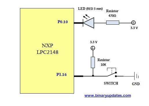
In this project, we’ll light up LED connected to Pin P0.10. When switch connected at Pin P1.16 been pressed. Releasing switch will effect to turn LED OFF. Now let’s go back to our development board which has couple of LEDs and SWITCHs on board. If in case your evaluation kit doesn’t have it then connect them externally. As shown in circuit diagram.
VIDEO: Add Switch to ARM7 LPC2148
Source Code: Add Switch to ARM7 LPC2148
#include <lpc214x.h>
int main(void)
{
     IO1DIR &= ~(1<<16); 	// explicitly making P1.16 as Input
     IO0DIR |= (1<<10);		// Configuring P0.10 as Output

     while(1)
     {
   if(!(IO1PIN & (1<<16))) // Evaluates to True for a 'LOW' on P1.16
    {
      IO0CLR |= (1<<10);	// drive P0.30 LOW, turn LED ON
    }else
   {
      IO0SET |= (1<<10);	// drive P0.30 HIGH, turn LED OFF
   }
     }
  return 0;
}
CODE EXPLANATION:
This complete program contains only few lines of code. Let me slice down into pieces to elaborate each line:
#include <lpc214x.h>
This include statement adds standard header file for all LPC214x series of microcontrollers. All register names has been defined in lpc214x.h file.
IO1DIR &= ~(1<<16); // explicitly making P1.16 as Input
We have switch connected to Pin P1.16 of LPC2148 Microcontroller. We have to explicitly set the direction of port pin in input mode. Even if by default it’s in input mode. Writing ‘0’ at P1.16 in the direction control register (i.e. IO1DIR) will configure P1.16 as input.
IO0DIR |= (1<<10); // Configuring P0.10 as Output
We have LED connected to Pin P0.10 of LPC2148 Microcontroller. To drive LED. We’ll first configure P0.10 into output mode. Writing ‘1’ to P0.10 in the direction control register (i.e. IO0DIR) will configure P0.10 as output.
while(1)
{
   if(!(IO1PIN & (1<<16)))      // Evaluates to True for a 'LOW' on P1.16
   {
  IO0CLR |= (1<<10);	// drive P0.30 LOW, turn LED ON
   }else
   {
  IO0SET |= (1<<10);	// drive P0.30 HIGH, turn LED OFF
   }
}
To download Project: Click Here
In this never ending while loop. If(!(IO1PIN & (1<<16))), this if statement evaluates to TRUE for a ‘LOW’ on Pin P1.16. Here in this project we continuously monitor the status of switch connected at Pin P1.16. ‘(1<<16)’ is simply 16th bit ‘1’ (i.e. 0x10000) and rest all bits are zeros. When ‘(1<<16)’ is ANDed with IO1PIN, it will make all other bits except 16th bit to ‘0’. The value of 16th bit will depend on IO1PIN’s 16th bit. If it’s ‘1’ (which means input is HIGH) then result after ANDing will be 0x10000 which is greater than zero and hence will evaluates to ‘TRUE’. Also when we use ‘!’ (i.e. Logical NOT) then ‘!(TRUE)’ evaluates to FALSE hence code is not executed for HIGH input. When P1.16 is given ‘LOW’ the corresponding bit in IO1PIN i.e. 16th bit will be set to 0. In this case the result of ‘IO1PIN&(1<<16)’ will be ‘0x0’ which evaluates to FALSE. Hence ‘!(FALSE)’ evaluates to TRUE and code inside ‘if’ block gets executed.
This is how you can capture input or simply add switch to ARM7 LPC2148 Microcontroller project. In next tutorial we’ll explore timer feature in LPC2148. We hope you’ll find this tutorial educational.