In this tutorial we will explore the use of PWM in LPC2148 ARM7 Microcontroller. Pulse Width Modulation (PWM) is very useful technique for controlling analog circuits with processors digital outputs. PWM used in a wide variety of applications ranging from measurement and communications to power control. As PWM is famous technique to generate a signal of varying duty cycle. Here we will use it to control brightness of LED using LPC2148.
Why we need PWM?
As we all know that microcontrollers do everything with ones and zeros. That means microcontroller works with 3.3V and 0V as digital 1 & 0. It can’t produce for example 1V or 2.5V or any other value different than 0V and 3.3V. Here PWM feature allows us to generate any voltage level between 0V and 3.3V. Now we will see how it’s been done using PWM so that we will control brightness of LED. This is probably the best way to see effect of PWM. Before we proceed any further let’s discuss little bit about duty cycle.

Duty Cycle:
When signal is HIGH, we call this “ON time”. To describe amount of “on time”(TON), we use the concept of duty cycle. Duty cycle is measured in percentage. The percentage duty cycle describe the performance of a digital signal ON over an interval or period of time. This period is the inverse of the frequency of the waveform. If digital signal spends half of time ON and remaining OFF, we would say this digital signal has duty cycle of 50%. If percentage is higher than 50% that means digital signal spends more time in HIGH state than LOW state then we would say duty cycle is higher than 50%.
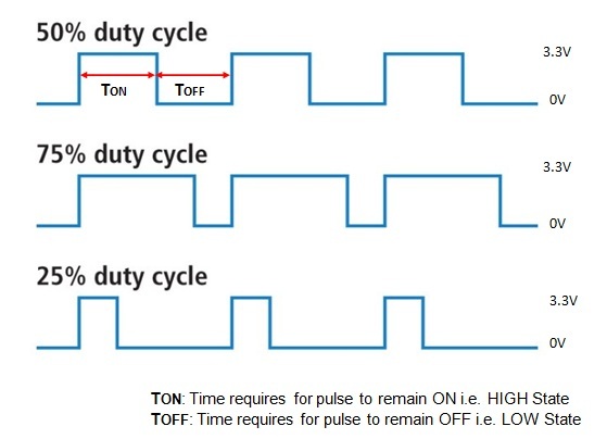
Above graph represents waveform of 50%, 75% & 25% duty cycle. 100% duty cycle would be the same as setting the voltage to 3.3V (HIGH). 0% duty cycle would be same as 0V or grounding the signal. The relation and calculation has been evaluated by following equations:
PWM in LPC2148 ARM7
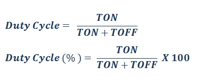
PWM in LPC2148 ARM7 looks complicated than the general purpose timers. However it is really an extra general purpose timer with some additional hardware. The PWM in LPC2148 is capable of producing six channels of single edge controlled PWM or three channel of dual edge controlled PWM. The Phillips LPC2148 has 6 channels of pulse width modulation. There are 7 registers to accommodate the PWM with register 0 being used to set base frequency (f =1/T). Thus since there is only one base frequency register all 6 channels must have base frequency.
As shown in figure above. PWM in LPC2148 can be single edge or double edge. In double edge PWM ending point of pulse and starting point of the pulse is a variable and can be set each cycle. In single edge PWM only the ending edge of the PWM is a variable and the starting edge is always set at the base frequency. Single edge requires one register (plus the base register) so that you can have 6-single edge channels of PWM on the LPC2148. For double edge PWM. You need a base register plus a starting edge register plus and ending edge register so that only 3-channels of double edge PWM is available on the LPC2148. You can mix single and double edge channels as long as you don’t run out of 6 available registers. Instead of spending more time I would prefer to start straight to implement example project. But before we get any further let’s have a quick look at PWM registers in LPC2148 Microcontroller.
Registers: PWM in LPC2148 ARM7
| PWMTCR | PWM Timer Control Register– PWMTCR is used to control the timer counter functions. The Timer Counter can be disable or reset through the PWMTCR. |
| PWMPR | PWM Prescale Register– The PWMTC (PWM Timer Counter) is incremented every PWMPR+1 cycles of PCLK. |
| PWMMR0-PWMMR6 | PWM Match Register 0- PWM Match Register 6– PWMMR0-6 can be enabled through PWMMCR to reset the PWMTC, stop both the PWMTC and PWMPC, and/or generate an interrupt when it matches the PWMTC. In addition, a match between PWMMR0-PWMMR6 and the PWMTC sets all PWM outputs that are single edge mode and sets PWM1 if it is in double-edge mode. |
| PWMMCR | PWM Match Control Register– The PWMMCR is used to control if an interrupt is generated and if the PWMTC is reset when match occurs. |
| PWMIR | PWM Interrupt Register– The PWMIR can be written to clear interrupt. The PWMIR can be read to identify which of the possible interrupt sources are pending. |
| PWMLER | PWM Latch Enable Register– Enables use of new PWM Match values |
| PWMPCR | PWM Control Register– Enables PWM outputs and selects PWM channel types as either single edge or double edge controlled. |
Here is an outline of steps necessary to setup PWM in LPC2148 ARM7 an output a single value:
- Setup the Pin Select Register to select PWM for the port we want
- Setup the Clock Divider Register for the PCLK (VPBDIV)
- Setup the PWM Timer Prescale Register
- Setup the IO direction for the PWM pin you plan to use as output
- Enable the particular PWM channel you want to use in the PWM Control Register(PWMCR)
- Set the maximum number of counts in one cycle. This is done in Match Register 0 (PWMMR0)
- Set the value for duty cycle in the particular match register you want to use (PWMMRx where “x” is from 1 to 6)
- Setup the PWM Match Control Register to cause a counter reset when the match register occurs (PWMMCR)
- Set the PWM latch Enable Register to enable the use of match value (PWMLER)
- Reset the timer counter using a bit in the PWM Timer Control Register (PWMTCR)
- Enable the timer counter and enable the PWM mode using the PWM timer control register (PWMTCR).
| OUTPUT | PWM1 | PWM2 | PWM3 | PWM4 | PWM5 | PWM6 |
| PIN NAME | P0.0 | P0.7 | P0.1 | P0.8 | P0.21 | P0.9 |
EXAMPLE PROJECT:
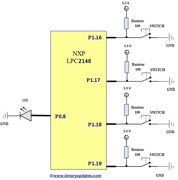
In this project we have to control the brightness of LED connected at Pin P0.8 of LPC2148. We will be using period of 10ms. We also have to connect Four Switches at Pin P1.16, P1.17, P1.18, and P1.19 which controls the pulse width and so when we press any switch among these. We will get equivalent brightness.
For this project we’ll modify code (according to our hardware connections) written by Mr. Umang Gajera. I will post one more tutorial where we will use PWM along with ADC to introduce dimming of LED with LPC2148.
Circuit Setup: PWM in LPC2148 ARM7
Program PWM in LPC2148 ARM7
/************************************************************/
/* PROJECT NAME: PWM (Pulse Width Modulation)	            */
/* Device:       LPC2148                				    */
/* Filename:     pwm.c                                   	*/
/* Language:     C                      	                */
/* Compiler:     Keil ARM				                    */
/* For more detail visit www.binaryupdates.com		        */
/************************************************************/

#include <lpc214x.h>

void initPWM(void);						// Initialize PWM
void initClocks(void); 	      // Setup PLL and Clock Frequency

int main(void)
{
  initClocks(); //Initialize CPU and Peripheral Clocks @ 60Mhz
  initPWM(); //Initialize PWM

  //IO1DIR = 0x1; This is not needed!
  //Also by default all pins are configured as Inputs after MCU Reset.

    while(1)
    {
    if( !((IO1PIN) & (1<<16)) ) // Check P1.16
    {
      PWMMR4 = 2500; //T-ON=25% , Hence 25% Bright
      PWMLER = (1<<4); //Update Latch Enable bit for PWMMR4
    }
    else if( !((IO1PIN) & (1<<17)) ) // Check P1.17
    {
      PWMMR4 = 5000; //50% Bright
      PWMLER = (1<<4);
    }
    else if( !((IO1PIN) & (1<<18)) ) // Check P1.18
    {
      PWMMR4 = 7500; //75% Bright
      PWMLER = (1<<4);
    }
    else if( !((IO1PIN) & (1<<19)) ) // Check P1.19
    {
      PWMMR4 = 10000; //100% Bright
      PWMLER = (1<<4);
    }
    }
    //return 0; //normally this wont execute ever
}

void initPWM(void)
{
  PINSEL0 = (PINSEL0 & ~(1 << 16)) | (1 << 17); // Select PWM4 output for Pin0.8
  PWMPCR = 0x0; //Select Single Edge PWM - by default its single Edged so this line can be removed
  PWMPR = 60-1; // 1 micro-second resolution
  PWMMR0 = 10000; // 10ms period duration
  PWMMR4 = 500; // 0.5ms - pulse duration i.e width (Brigtness level)
  PWMMCR = (1<<1); // Reset PWMTC on PWMMR0 match
  PWMLER = (1<<0)|(1<<4); // update MR0 and MR4
  PWMPCR = (1<<12); // enable PWM output
  PWMTCR = (1<<1) ; //Reset PWM TC & PR

  //Now , the final moment - enable everything
  PWMTCR = (1<<0) | (1<<3); // enable counters and PWM Mode

  //PWM Generation goes active now - LED must be 25% Bright after boot!!
  //Now you can get the PWM output at Pin P0.8!
}

void initClocks(void)
{
  PLL0CON = 0x01;   //Enable PLL
  PLL0CFG = 0x24;   //Multiplier and divider setup
  PLL0FEED = 0xAA;  //Feed sequence
  PLL0FEED = 0x55;

  while(!(PLL0STAT & 0x00000400)); //is locked?

  PLL0CON = 0x03;   //Connect PLL after PLL is locked
  PLL0FEED = 0xAA;  //Feed sequence
  PLL0FEED = 0x55;
  VPBDIV = 0x01;    // PCLK is same as CCLK i.e.60 MHz
}
Download Project: Click Here
Code Explanation:
In this code snippet we will discuss void initPWM(void) routine. Remaining things has already been covered in previous tutorials and also well commented in code itself. Basically in this function void initPWM(void) we have to setup and configure PWM channel of LPC2148.
PINSEL0 = (PINSEL0 & ~(1 << 16)) | (1 << 17);
To use PWM4 channel at Pin P0.8 of LPC2148. We have to set bit-16 to become ‘0’ & bit-17 to become ‘1’ into PINSEL0 register. This enables us to use PWM4.
PWMPCR = 0x0;
Here in PWMPCR register we’ve to select either single edge pwm or double edge pwm outputs. By default it’s single edge so this line can be removed. Now here come important part:
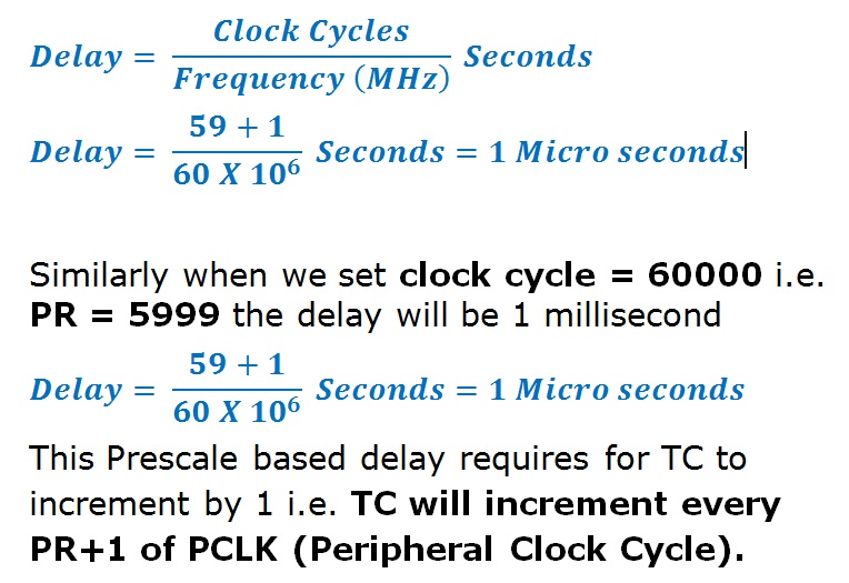
PWMPR = 60-1;
As we’ve PCLK running at 60 MHz, If we use Clock Cycle=60 then PR=59 i.e. (60-1). So we get resolution of exact 1 micro second.
This is how we can use PWM in LPC2148 ARM7 Microcontroller to control the brightness of LED. We can do many things by generation of varying duty cycle. We will discuss double edge PWM in our future post because it’s not in the scope of this tutorial. If you have any questions then feel free to leave a comment.