This tutorial is about Timer and Counter in AVR Atmega32A Microcontroller. Timer is a fairly complicated topic in microcontroller. Instead of repeating content from datasheet and discussing register description we’ll focus on basic details. In the end we will look at real world example along with circuit diagram and code snippet. All microcontroller works at predefined clock frequency, they all have provision to set up timer for various applications. Timers can tell time and count. These timing and counting allows really cool things like counting, monitoring external event, frequency generation, controlling brightness of LED by PWM, controlling angle of servo shaft, receiving sensor data that transmit in PWM and many more…..

All microcontrollers have clock in them as an in-built peripheral and also one can add external crystal or resonator to generate more accurate counts. Microcontroller needs a clock to drive process that is happening by our program. The program or instruction is executed by microcontroller in rhythm with clock. It’s important to understand that timer and counter function In microcontroller simply count in synchronous with microcontrollers clock. At other hand timers can run asynchronously with AVR core. It means timers are totally independent of CPU. Here in this case, we will use AVR Atmega32A microcontroller which has two 8-bit and one 16-bit timer. This means we have total 3 timers in our chip. The two 8-bit timer-counter counts up to 255 and one 16-bit timer counts up to 65535.
| Timer 0 | 8-bit counter | Counts up to 255 |
| Timer 1 | 16-bit counter | Counts up to 65535 |
| Timer 2 | 8-bit counter | Counts up to 255 |
Timers are usually used in one of following mode:
- Normal Mode
- CTC Mode
- Fast PWM Mode
- Phase Correct PWM Mode
As we move further with tutorial series we will be using most of timer modes but for this article we will limits to an concept of prescaler and CTC mode.
Prescaler, why we need?
Prescaling is a process of generating a clock for timer by F_CPU clock. It also can be used for counter to skip certain number of microcontroller clock ticks. AVR microcontroller allows prescaling or skipping number of 8, 64, 256, 1024. For example: if 64 is set as a prescaling value then counter will count every time the clock ticks 64 times that means in one second where microcontroller clock ticks one million times (as default) the counter will count only upto 15,625 (1000000/64=15,625). You could see if counter count up to 15,625 then you can able to blink LED at every second.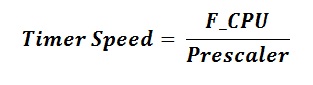
CTC Mode: (Clear Timer on compare Match)
This is mode of operation in AVR, which we will be using often. Timer in compare mode or to say CTC mode, instead of counting until overflow occurs. The timer compares its count to the value that previously stored in register. When count matches that value then timer can either set a flag or trigger an interrupt same as happen in case of overflow.
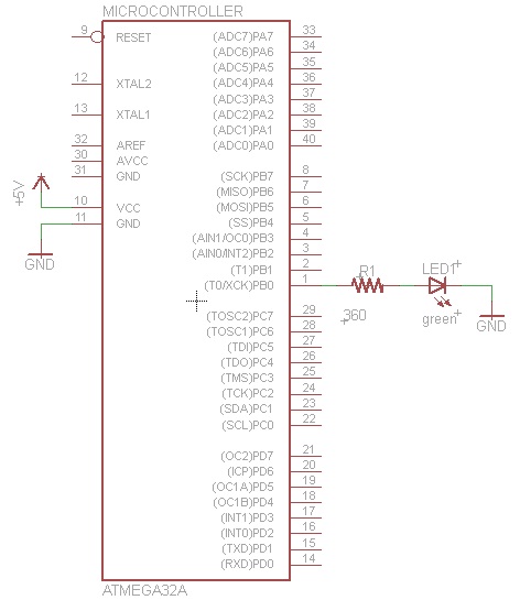
Example Tutorial: In this example, we are going to use timer-1. This is 16-bit timer and to keep simple and short we are using no-prescaler. In this case we have make use of timer counter control register TCCR1B and set CS10 bit to high (1). Refer datasheet page number 115.
We have connected Greed LED and Resistance (360Ω) to Pin Number 1 which is PB0 Pin of a Microcontroller.
Source Code: Timer in AVR Atmega32A Microcontroller
/*
 * Example Project: TimerTest.c
 * Created: 17-06-2013 19:01:38
 * Author: UMESH
 */

#include <avr/io.h>

int main(void)
{
  //Initialize port for LEDs
  DDRB = 0b00000001;
  PORTB = 0b00000000;
  TCCR1B |= 1<<CS10;
  int repeatCount = 0;
  while(1)
  {
    if (TCNT1 > 10000)
    {
      repeatCount++;
      TCNT1 = 0;
      if (repeatCount > 100)
      {
        repeatCount = 0;
        PORTB ^= 1 << PINB0;
      }
    }
  // Count and turn an LED ON and OFF
  }
}
Short Explanation:
Here one can see two loops inside never ending while loop. Outer loop inside while loop is used to count TCNT1 register upto 10000 counts. As we’re using internal clock 1 MHz and it ticks 1000000 times in each clock cycle. The inner if statement takes two variable “repeatCount” and used it to scale 100 times so now LED blink is visible to normal eyes.
I recommend you to try this example by your own and play little bit around with the code by modifying some parameters to get inside detail of how timer works with internal clock. I hope you will find this tutorial educational and entertaining.