In previous tutorial, we have learned how to program most basic peripheral i.e. GPIO Port Pin of Microcontroller. Here in this tutorial, we’ll write simple application which will introduce you timer interrupt in LPC1768 Microcontroller.
Timer is internal peripheral in LPC1768. They use CPU clock to keep track of time and count. Timer enhances use of microcontroller in number of ways. Timers send periodic events and make precise measurements. It makes time available for your microcontroller project. This means you can start using temporal information in your program, without having to use unwieldy spin loops. In this tutorial our goal is to set up a timer and then with the help of interrupts we’ll blink the LED.

Timers in LPC1768 Basics
In LPC1768 Microcontroller there are four timers Timer 0, Timer1, Timer2 and Timer3. These are 32-bit timer/counter with programmable 32-bit prescaler. All are identical but can have options to set them independently. And can be used without interfering with each other.
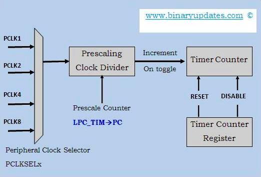
All timer’s are built around an internal Timer Counter (TC), which is a 32-bit register and incremented periodically. The rate of change is derived from the current speed of the CPU clock you’ve connected up and what the Prescale Counter is set to. There is nothing more to it than that. The Prescale Counter is clock divider. As mentioned earlier, Timer Counter is a 32-bit register and it counts in range from 0x00000000 to 0xFFFFFFFF.
Before we get into programming fundamentals, it’s important to understand powering procedure for LPC1768 microcontroller. Powering device is necessary before choosing the peripheral clock and setting the prescale register. We need to turn on timer. Upon RESET most of the LPC’s peripherals are OFF and aren’t being supplied power by microcontroller.
This can save a lot of power, but few core peripherals are turned on when the LPC starts, among these GPIO, TIMER0 and TIMER1. This means that TIMER2 and TIMER3 start off and if you need them in your application then you’ll have to turn them on. Additionally, if you don’t need TIMER0 or TIMER1, you can even turn them OFF to save some power.
Usually, power control is considered a system feature and is controlled by register LPC_SC–>PCONP. We’ll see in details while discussing program in later part of this tutorial. For more detail description on timer, Please visit User Manual UM10360 [Chapter: 21, Page No: 499].
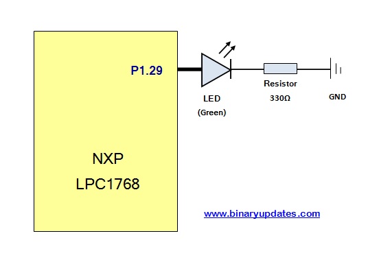
Now let’s hook up LED to Pin P1.29. Please have a reference of Circuit Set:
Let’s have a look at code snippet which uses TIMER0 to blink LED about every 1 Second,
#include "LPC17xx.h"

int main (void)
{
	LPC_SC->PCONP |= 1 << 1;      // Power up Timer 0
	LPC_SC->PCLKSEL0 |= 1 << 2;   // Clock for timer = CCLK
	LPC_TIM0->MR0 = 1 << 23;      // Suitable for LED
	LPC_TIM0->MCR |= 1 << 0;      // Interrupt on Match0 compare
	LPC_TIM0->MCR |= 1 << 1;      // Reset timer on Match 0.
	LPC_TIM0->TCR |= 1 << 1;      // Reset Timer0
	LPC_TIM0->TCR &= ~(1 << 1);   // stop resetting the timer.
	NVIC_EnableIRQ(TIMER0_IRQn);  // Enable timer interrupt
	LPC_TIM0->TCR |= 1 << 0;      // Start timer

	LPC_SC->PCONP |= ( 1 << 15 ); // power up GPIO
	LPC_GPIO1->FIODIR |= 1 << 29; // LED is connected to P1.29
	while(1)
	{
		//do nothing
	}
	return 0;

}
void TIMER0_IRQHandler (void)
{
    if((LPC_TIM0->IR & 0x01) == 0x01) 	// if MR0 interrupt
    {
        LPC_TIM0->IR |= 1 << 0; 	// Clear MR0 interrupt flag
        LPC_GPIO1->FIOPIN ^= 1 << 29; 	// Toggle the LED
    }
}
Code Explanation:
Let me slice down complete program into pieces for explanation,
LPC_SC->PCONP |= 1 << 1;     // Power up Timer 0
LPC_SC->PCLKSEL0 |= 1 << 2;  // Clock for timer = CCLK
Power the device; here we set the bit in LPC_SC–>PCONP for TIMER0, to turn power on. This is essentially the same for most of other peripheral. After enabling power option we required to set the clock for TIMER0 to turn off CPU clock. Read more in User Manual [page No: 57, Table:40 and Table: 42].
LPC_TIM0->MR0 = 1 << 23;    // Suitable for LED
LPC_TIM0->MCR |= 1 << 0;    // Interrupt on Match0 compare
LPC_TIM0->MCR |= 1 << 1;    // Reset timer on Match 0.
LPC_TIM0->TCR |= 1 << 1;    // Reset Timer0
LPC_TIM0->TCR &= ~(1 << 1); // stop resetting the timer.
NVIC_EnableIRQ(TIMER0_IRQn); // Enable timer interrupt
LPC_TIM0->TCR |= 1 << 0;    // Start timer
In LPC1768 we have 4 match registers for each Timer. These match registers can be used for several reasons like, to reset the timer, generate interrupt, stop the timer, to generate timing signal on external pin. Here in this case, Match0 is set to 2^23 (Note: because startup code gets the chip running at 100 MHz by default, 1 tick or period of timer = 1/100MHz = 10ns, hence (2^23+1) ticks = 0.08388609 seconds. You’ll see LED blinking after every 0.083 sec. everything else in this section is well commented in code & self explanatory.
void TIMER0_IRQHandler (void)
{
    if((LPC_TIM0->IR & 0x01) == 0x01) 	// if MR0 interrupt
    {
        LPC_TIM0->IR |= 1 << 0;         // Clear MR0 interrupt flag
        LPC_GPIO1->FIOPIN ^= 1 << 29; 	// Toggle the LED
    }
}
Inside the interrupt handler, we check for source of interrupt. In this case, TIMER0 can produce interrupt from Match0 and then toggle the LED. We’ll discuss more about Interrupt feature of Cortex-M3 microcontroller in future. I hope this tutorial will help you to understand timer interrupt in LPC1768 Microcontroller. You can download project files click button below: