In previous post, we found how to program LPC1768 microcontroller to drive LED. This has been done by configuring GPIO into output mode. Adding button or switch to circuit enables the microcontroller to receive human input. Here in this tutorial, we’ll discuss how to add button switch to LPC1768 Microcontroller project. In this task we will program microcontroller pins to input. Our goal is that, LED should turn OFF when switch is pressed.

Circuit Connection: Add Button Switch to LPC1768 Microcontroller
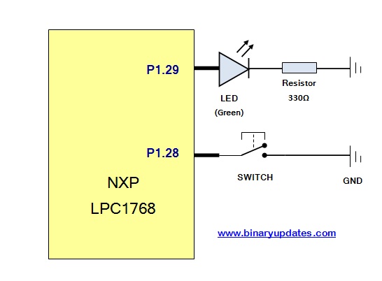
Let’s go back to our development board which already has LED connected to Pin P1.29. To add switch at P1.28 Pin of microcontroller, we have to prototype small circuit on breadboard. Just hook up LED (If in case not available on your board) and button switch. Here is circuit diagram for your reference,
To use GPIO port pin P1.28 as input to read switch state. It’s required to set the GPIO port into input mode. We’ll discuss more about that later on. Let’s have a look into programming part of application:
Source Code: Add Button Switch to LPC1768 Microcontroller
#include "lpc17xx.h"

int getPinState(int pinNumber);		// Method prototypes

int main(void)
{

  LPC_GPIO1->FIODIR &= ~(1 << 28); 	// Set buttons as input
  LPC_GPIO1->FIODIR |= (1 << 29); 	// Set LEDs as output
	LPC_GPIO1->FIOPIN |= (1 << 29); // Turn both LEDS on

  while (1)
  {
    if (getPinState(28))			// Check button pressed
    {
      // Turn LED off
       LPC_GPIO1->FIOSET = (1 << 29);
    }
    else
    {
      // Turn LED on
      LPC_GPIO1->FIOCLR = (1 << 29);
    }
  }
}

int getPinState(int pinNumber)
{

  int pinBlockState = LPC_GPIO1->FIOPIN; // Read current state of pins
  // Read the value of 'pinNumber'
  int pinState = (pinBlockState & (1 << pinNumber)) ? 1 : 0;
  return pinState;											// Return the value of pinState
}
Download Files: Add Button Switch to LPC1768 Microcontroller Project.
Code Explanation:
After careful observation, you can say that program is not much different from previous example. The only addition is of extra function i.e. int getPinState(int pinNumber). Let’s discuss each line of program step-by-step:
LPC_GPIO1->FIODIR &= ~(1 << 28);
Here we have set the bit low which set direction of pin P1.28 to input mode. As we have connected button switch to P1.28.
LPC_GPIO1->FIODIR |= (1 << 29);
Set the port pin P1.29 to HIGH. To drive LED at any pin we required to set direction into output mode.
LPC_GPIO1->FIOPIN |= (1 << 29);
Here we set pin P1.29 to logic “HIGH”. As we decided to turn LED ON from beginning of program flow.
while (1)
  {
    if (getPinState(28))
    {
       // Turn LED1 off
       LPC_GPIO1->FIOSET = (1 << 29);
    }
    else
    {
      // Turn LED1 on
      LPC_GPIO1->FIOCLR = (1 << 29);
    }
  }
This never ending loop keep checking status of pin P1.28 i.e. Switch. If Switch Released i.e. logic “HIGH”, turns the LED ON. When Switch Pressed i.e. logic “LOW”, turn the LED OFF. Now let’s get into key part of this program.
int getPinState(int pinNumber)
{
  int pinBlockState = LPC_GPIO1->FIOPIN;
  // Read the value of 'pinNumber'
  int pinState = (pinBlockState & (1 << pinNumber)) ? 1:0;
  // Return the value of pinState
  return pinState;
}
getPinState(int pinNumber) function returns the current state of pin. Here in this case we have used getPinState(28) in while loop which reads the status of GPIO port pin P1.28 and returns status either HIGH(“1”) or LOW(“0”). This pin status used further to turn LED either ON or OFF.
When you build and run this program on your LPC1768 device. You will find LED will stays turned ON all the time. Just press switch to see effect which turn LED OFF until you hold switch to LOW.