This article is about different types of capacitor. Any piece of electronic circuit, equipment have variety of capacitors inside it. When comes to selection of capacitor for electronics circuit design, we have many options. There are several types of capacitor depending on functionality, electrical parameters, composition, size etc. Let’s discuss about them.
Table of Contents
Types of Capacitor
Capacitors comes in variety of shapes, sizes and electrical ratings. You may see same type of capacitor in axial, radial as well as surface mount (SMD) type. Depending on value, capacitors fall into two main categories: fixed value capacitors and variable capacitor. These types can be further categorize on the basis of polarity and dielectric material used.
Fixed Capacitors
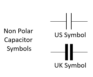
Many types of fixed capacitors are used in electronics as well as electrical circuits. They are designed to have fixed value of capacitance. These capacitors can be classified according to polarity. The polarized and non-polarized fixed capacitor can be further classified by dielectric material used. Usually, fixed capacitor are named as per dielectric material used in them.
Ceramic Capacitor
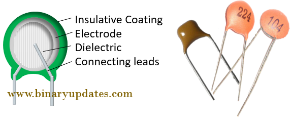
They are non-polarized. Their value ranges from pF to µF. They are available in wide variety of working voltage (from few volt to kilo volt). Ceramic capacitors are divided into two categories, namely disc capacitors and multi-layer capacitors. The disc type capacitors have pretty simple construction. They have a small ceramic disc coated with silver on both side, hence also called as disc capacitors. This disc and silver coating acts as ceramic electric and electrodes respectively. The disc and silver electrode assembly is coated with insulator for protection. The capacitance value of disc capacitors ranges in between 0.5 to 1600 pF. The dielectric can also be in plate shape for plate, tabular ceramic capacitor. These capacitors capacitance ranges in between 1 pF to 1 µF. the breakdown voltage ranges in between 500 V to 20 kV. The multi-layer ceramic capacitors are called as MLCC – Multi-layer Ceramic Capacitor, used to achieve high capacitance. The high dielectric constant increases capacitance of ceramic capacitors while keeping physical size small. These capacitors perform well at high frequencies. These are general purpose capacitors and mainly used to remove noise (E.g. in Microcontroller key de-bouncing circuit, with MAX232 IC, with crystal oscillator). As ceramic capacitors are non-polarized; they can be used in both DC as well as AC circuits.
Film Capacitor
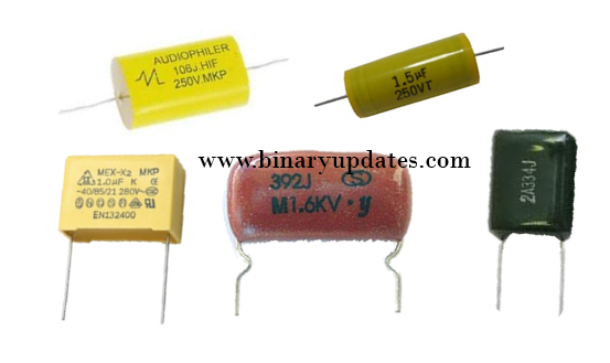
They are also known as film caps or power film capacitors. Film capacitors are made of plastic (or paper, metal film) film covered by metallic electrodes, placed into a winding, with leads attached, and then enclosed in casing. The various film capacitors get their name on the basis of dielectric used. Capacitors with polyester (mylar), polystyrene, polycarbonate or teflon as dielectric material are generally called as plastic capacitor. The capacitance of foil or metalized capacitor lies in between 100 pF to 100 uF, while paper capacitor value is in between 1 nF to 1 µF. They have higher working voltage than ceramic capacitors. The voltage range is around 200 V to 1600 V for paper type and 50 V to 600 V for foil type film capacitors. They are widely used in power electronics because of their low cost and superior characteristics such as temperature stability, low self-inductance and ESR. Film capacitors are not polarized, hence can be used in both AC and DC circuits.
Mica Capacitor
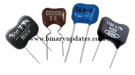
These capacitors has mica as dielectric material covered with thin silver layer. Hence these capacitors are also called as silver mica capacitors. Mica capacitors are available in the range between a few pF to thousand pF with voltage rating in between few hundred volt to thousand volt. The dielectric in mica capacitor is used as stacked sheets. The capacitance of mica capacitors ranges from 10 pF to 5000 pF and breakdown voltage is similar to ceramic capacitors. Mica capacitors offer high precision, reliability and stability. They are available in small values and are generally used at high frequencies and in situations where low losses and low capacitor change over time are required.
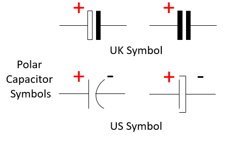
Electrolytic Capacitor
Electrolytic or Polar capacitors are widely used in electronics circuit because of their low cost, high capacitance and ease of availability. They comes cylindrical metal shape with outer plastic sheath. These types of capacitors is used as ripple filter in power supply, as a filter to bypass low frequency signals. Electrolytic capacitors are usually measured in microfarads and rarely in farads. These capacitor are polarized, hence they are mostly used in circuits where both AC and DC signals are used.
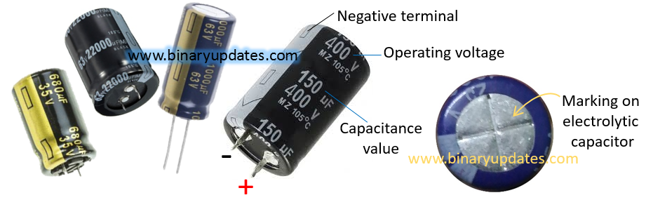
Aluminium Electrolytic Capacitor
Aluminium is used in construction of aluminium electrolytic capacitors. These capacitors are available with capacitance in between 1 µF to 47000 µF. They have maximum breakdown voltage around 400 V. They have high ripple current capability, high leakage, poor tolerance and lifetime. Aluminium electrolytic capacitors have Poor performance at high frequencies due to ESR. The size of electrolytic capacitors increases with increase in capacitance. These capacitors are widely used in audio amplifiers to reduce hum noise. The aluminium electrolytic capacitor has one special construction arrangement on top of it. You may be wondering that, why such marking is there? Well, this marking related to protection of you. Imaging, what will happen if electrolytic capacitor is connected with wrong polarity? The reverse polarity connection creates gas and increases temperature in capacitor. This permanently damages and may explode capacitor. Thanks to electronics component designers, electrolytic capacitors have thin casing (marking) on top side which break upwards and allows this gas pressure to get release and prevent capacitor from getting explode.
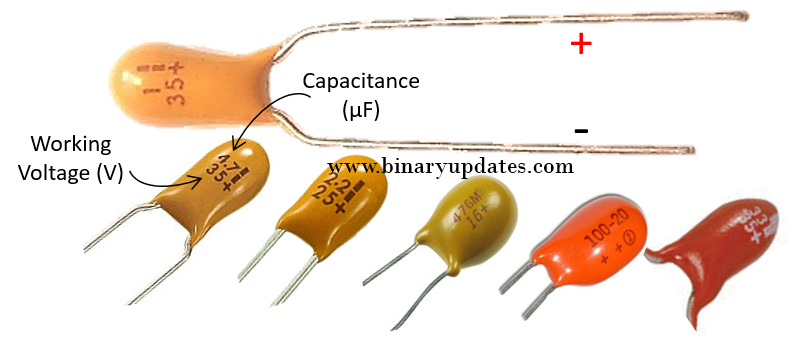
Tantalum Electrolytic Capacitor
A tantalum metal is used in construction of tantalum electrolytic capacitors. These capacitors are available with capacitance in between 47 nF to 330 µF. Generally they have low working voltage in between 1.5 V to 40 V. Tantalum electrolytic capacitors have low ripple current capability, low leakage and highly tolerant to reverse and over voltage. They have poor performance at high frequencies. The high capacitance in small size makes tantalum capacitor, first choice for electronics circuit designer to use in complex circuits such as mother board. They are also useful in military application and extremely stable audio amplifiers.
Variable Capacitors
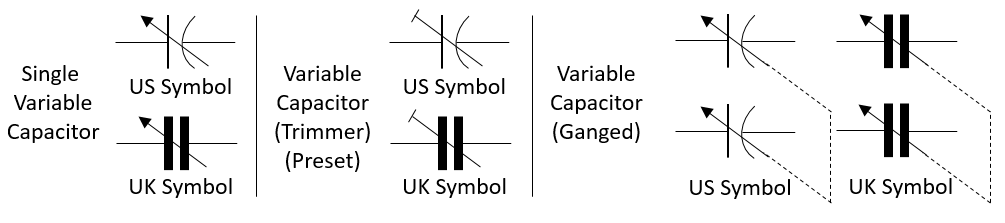
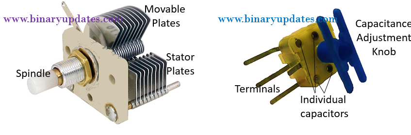
They are designed to have variable value of capacitance. In this type area between two plates is adjusted to change capacitance of capacitor. The construction of tuning capacitors consists of two important mechanical movements i.e. angle of spindle movement and plate movements. In variable capacitor, conductive plates in air capacitor are meshed (cross together). The stator (stationary) plates pairs with movable plates through spindle movement. Capacitance is varied by spindle movement (shaft rotation) to make the movable plates mesh with the stator plates. The change in capacitance by such mechanical structure can be of following types – linear (spindle movement ∝ capacitance), logarithmic (spindle movement ∝ percentage change of frequency), even (spindle movement ∝ capacitance and frequency) and square law (square of spindle movement ∝ capacitance). Variable capacitors are generally used in LC circuits for tuning frequency in radios, hence such capacitors also called as tuning capacitors.

Air Capacitor
These are simplest variable non-polarized capacitors. The capacitance of air capacitor is small, about 100 pF to 1 nF. Air capacitors uses air as dielectric in two conductive plates. The operating voltage of air capacitor is in between tens to a thousands of volts. The breakdown voltage of air as dielectric is lower hence there is a change of electrical breakdown in capacitor. This leads to faulty working of capacitor. Hence sometimes vacuum is created between capacitor plates which has dielectric constant nearly the same as that of air. The breakdown voltage is higher for vacuum hence less chance of electrical breakdown. Sometimes the air capacitor is also called as “Gang capacitor”. A gang capacitor is a combination of two or more variable capacitors mounted on a common shaft to. This adjustment allows simultaneous change in capacitance of grouped capacitors. You can see in picture the gang capacitor has many output leads, this leads get gang (grouped) by adjustment screw for changing the capacitance. It is used in AM and FM radio circuits.
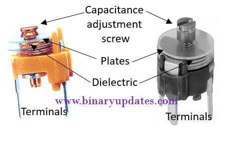
Trimmer Capacitor
Similar to trimmer resistors capacitors also have trimmer or preset capacitors. They are non-polarized. Trimmer capacitors are used when there is no need to vary capacitance again after initial adjustment. This capacitor has dielectric placed between two parallel facing conductive plates. Generally, trimmers capacitance is change by changing overlap area between plates with provided adjustment screw. Trimmers uses a sheet of dielectric material such as mica, mylar etc. The maximum value of trimmers is in between few pF to about 200 pF. These capacitors are design to handle low to moderate voltages, and are highly efficient. To vary capacitance of trimmer capacitors it is advised to use non-metallic tools, since use of metal may affect capacitance value.
Characteristics and Specifications of Capacitor
Each capacitor type has its own set of specifications and characteristics. Hence, one has to be careful while choosing a capacitor. The specifications of capacitor can be observed from information printed on its outer body and its characteristics can be understood by finding details about its composition and physical structure. Let us see which factors are need to be consider while selecting a capacitor.
1. Equivalent series resistance – Every metal have some amount of resistance. The capacitor has metal leads and they have tiny resistance (about 0.01 Ω). This resistance together with current through capacitor, creates heat i.e. power loss.
2. Precision – Capacitors do not have exact or precise capacitance. The variation in value of capacitance is called as tolerance of capacitor. This value depends on type and ranges from ±1% to ±20% of the actual capacitor value.
3. Voltage rating – Depending on type, capacitors have maximum rate voltage that can be applied across it. This voltage rating may vary from 1V to 100V.
4. Size – The capacitor size is related to capacitance value and it physical size. Higher the value of capacitance and voltage rating bigger is its size.
5. Stability – The stability of capacitor defines the change in value of capacitance with temperature and time.
6. Leakage current – Practically, there is tiny value of current (in mA or nA) leaking through capacitor. This leakage leads to decrease in capacitor stored energy and it gradually discharge capacitor.
7. Aging – The capacitance of capacitor decreases over time, this is known as aging.
8. Application – Depending on type capacitors have variety of applications. E.g. filter circuit, tuning circuit, bypass capacitor etc.
This is it for this post. I believe now you’re familiar with different types of capacitor and their significance. In next post, we’ll learn about color coding of capacitors. Thanks for reading. Keep visiting.